North American calculation exchange
Match the catalog family, optic and lumen package before import. A valid file format does not establish that the data belongs to the proposed configuration.
Photometric Resources
Use IES and LDT data with documented optic, output and mounting context. This resource center separates calculation inputs, product evidence and specification notes so design teams can see what is known—and what still needs confirmation.
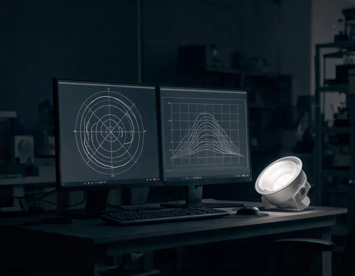
Match the catalog family, optic and lumen package before import. A valid file format does not establish that the data belongs to the proposed configuration.
Review geometry, lamp or module context and symmetry fields. Confirm whether the project tool interprets coordinate conventions as expected.
Look for the tested sample description, input conditions and reported quantities. Do not transfer results across driver or output options without evidence.
Relate projected maintenance to LM-80 data, thermal conditions and permitted projection multiples. L70 is not an unconditional installation warranty.
Downloads are grouped by verification purpose, not by marketing theme. Request the current package where the project configuration is not shown.
IES or LDT file, optic identifier and output context.
Driver interface, power factor, dimming and surge information where available.
Dimensions, mounting constraints, clearances and commissioning references.
Record family, optic, output, CCT, CRI, driver and control option. Similar product names are not sufficient identifiers.
Check sample description, input voltage, ambient condition, orientation and measurement method. LM-79 context supports comparison only when these details are compatible.
Import the file, enter room dimensions, reflectance, maintenance assumptions and task planes, then inspect illuminance and luminance-related outcomes. Repeating the process requires the same inputs and software settings.
Verify applicable UL, CE or RoHS evidence for the region and assembly. Field conditions, mounting tolerances and controls commissioning remain limitations outside the photometric file.
Centralized architecture can simplify unified policies and reporting, but it concentrates commissioning dependencies. Distributed architecture supports zone flexibility and local fault isolation, while requiring a deliberate addressing and maintenance strategy. Compare network topology, fallback behavior, expansion needs and ownership instead of treating either model as universally superior.
Send the family, optic, output and control option so the project team can qualify the available evidence.
Request Photometric Evidence